
Why Does 9729 Audio CablesKeep Picking Up Noise in Industrial Environments?
You pull another cable run, fire up the test scope, and the waveform still looks like a seismograph during an earthquake. Meanwhile your competitor's system next door runs clean. The difference often comes down to cable design choices you made six months ago during the BOM review.
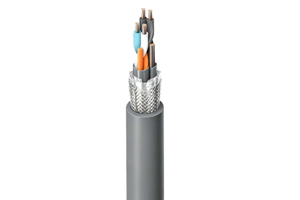
The 9729 Audio Cables solves crosstalk and signal drift by wrapping each twisted pair in individual foil shields and using Datalene insulation with capacitance below 30 pF/m1. This construction keeps RS232/422 data clean alongside analog 4-20mA sensor loops even when bundled in the same tray for hundreds of meters.
I remember a project where we ran four analog pressure transmitters and two RS422 encoder feeds through a single conduit. The system worked fine in the lab. Three weeks after commissioning the encoders started throwing CRC errors every few seconds. We swapped PLCs, tightened connectors, even replaced the encoders. The root cause was cable coupling we never tested under real EMI conditions.
What Makes 9729 Audio Cables Different from Standard Multi-Pair Control Cable?
You see "multi-pair shielded cable" on a datasheet and assume it will handle mixed signals. Most control cables use a single overall foil or braid that does nothing to stop pair-to-pair crosstalk inside the jacket.
9729 Audio Cables wraps each twisted pair in its own 100% coverage aluminum-polyester foil before applying the overall tinned-copper braid. This dual-layer approach isolates digital edges from sensitive analog returns and keeps high-speed differential signals from bleeding into adjacent pairs.
Standard cables group all pairs under one shield. When a fast RS422 transition occurs the return current couples into neighboring pairs through common-impedance paths. You see this as unexplained offset drift on your 4-20mA loop or phantom counts on an encoder. The 9729 construction blocks that path.
Comparing Shield Configurations
| Cable Type | Per-Pair Shield | Overall Shield | Crosstalk at 1 MHz | Typical Application |
|---|---|---|---|---|
| Standard multi-pair | None | Foil or braid | -30 dB | General I/O, low speed |
| 9729 Audio Cables | 100% foil each pair | Tinned-copper braid | -60 dB | Mixed analog/digital, RS422/485 |
| Instrumentation quad | Star-quad twist | Foil + drain | -50 dB | Balanced audio, low-level analog |
The -60 dB crosstalk spec means interfering signals are one thousand times weaker2. In practical terms you can run a 115 kbps RS422 link in the pair next to a 4-20mA loop reading a flow transmitter without seeing noise spikes when the data toggles.
I tested this on a water treatment skid with six transmitters and three actuator position encoders. We bundled all nine pairs in 9729 Audio Cables and ran them 180 meters from the field junction box to the control room. The analog loops held ±0.02 mA stability even during peak encoder activity. The previous installation used a cheaper 18 AWG bundled cable and showed ±0.15 mA noise.
How Does Low Capacitance Prevent Signal Distortion on Long Runs?
You lay out a 300-meter run for an RS422 link. The datasheet says the transmitter can drive 1200 meters. Six months later you see occasional frame errors during peak traffic even though the physical layer tests pass.
Cable capacitance loads the driver and rounds off fast edges3. Belden 9729 uses foamed polyethylene Datalene insulation to achieve typical capacitance of 16 pF/ft (52 pF/m), allowing RS422 systems to maintain clean edges at 10 Mbps over hundreds of meters without expensive line drivers.
Capacitance matters because every picofarad you add increases the RC time constant at the receiver. A 300-meter run of standard 30 pF/ft cable presents about 9 nF load. At 10 Mbps your bit period is only 100 ns. The driver must charge that capacitance through its output impedance plus the 100Ω differential line. If the rise time stretches beyond 20% of the bit period you start closing your eye diagram.
Cable Capacitance Impact on Baud Rate
| Cable Length | Standard Cable (30 pF/ft) | Belden 9729 (16 pF/ft) | Maximum Clean Baud (9729) |
|---|---|---|---|
| 100 m | 3.0 nF | 1.6 nF | 10 Mbps |
| 200 m | 6.0 nF | 3.2 nF | 5 Mbps |
| 400 m | 12.0 nF | 6.4 nF | 2 Mbps |
| 600 m | 18.0 nF | 9.6 nF | 1 Mbps |
The table shows that at 400 meters standard cable forces you down to 2 Mbps while 9497 Audio Cables can still support 5 Mbps. This difference becomes critical when you need to push encoder data from a remote gantry or upgrade an existing run to a faster protocol without pulling new cable.
I worked on a packaging line retrofit where the customer wanted to replace parallel encoder interfaces with RS422 to reduce wiring. The existing conduit had space for only one multi-pair cable. We tried a standard 22 AWG cable first and could not get stable operation above 2 Mbps at 250 meters. Switching to 9497 Audio Cables let us run 5 Mbps with 40% eye-diagram margin.
Why Does Everyone Confuse RS422 and RS485 Cable Impedance?
You order cable for an RS422 network and receive spools marked "RS485." The vendor says they are the same. Three months later you chase intermittent errors that only appear when multiple nodes transmit.
RS422 requires 100Ω differential impedance4 because it uses separate transmit and receive pairs. RS485 uses 120Ω because it shares a single half-duplex pair among multiple transceivers5. Belden 9729 is designed as a 100Ω cable for point-to-point and multi-drop RS422 systems, not for RS485 bus topologies.
The impedance difference comes from the way the standards evolved. RS422 assumes you have one driver and up to ten receivers on separate wire pairs. The termination resistor matches the cable to prevent reflections. RS485 extends that to allow multiple drivers on a shared pair using tri-state logic. The 120Ω impedance became the standard for that shared bus.
Comparing RS422 and RS485 Cable Requirements
| Parameter | RS422 (9729) | RS485 |
|---|---|---|
| Differential impedance | 100Ω ±10Ω | 120Ω ±10Ω |
| Topology | Point-to-point or star | Multi-drop bus |
| Termination | 100Ω at receiver | 120Ω at each end |
| Maximum nodes | 10 receivers | 32 transceivers |
| Typical capacitance | 16 pF/ft | 16-20 pF/ft |
| Shield per pair | Yes (9729) | Optional |
If you connect 9729 Audio Cables in an RS485 network you create a 20% impedance mismatch. At low baud rates this causes minor reflections. At 10 Mbps the reflections overlap with the next bit and create intersymbol interference. I have seen systems work fine at 115 kbps with mismatched cable but fail certification testing at 2 Mbps.
A customer called me after a failed RS485 Modbus network kept dropping nodes. They had used 9729 Audio Cables because the spec sheet said "digital communication cable." RS485 needs 120Ω cable. We replaced it with proper 120Ω twisted pair and the network became stable. If your project specifies RS422 point-to-point links use 9729. If you need RS485 multi-drop specify 120Ω cable instead.
You win a contract to supply control panels for three facilities in Texas, Germany and Manchester. Each site has different cable certification requirements. You spend two days cross-referencing standards to find a cable that ships to all three.
9729 Audio Cables variants rated UL Type CM for North America6, CPR Eca for EU installations, and UKCA-marked versions for post-Brexit UK projects. All versions meet RoHS lead-free requirements and share identical electrical specs, simplifying multi-region BOM management.
The challenge comes from regional fire and safety codes. UL CM means the cable passed vertical flame testing for general indoor use in the USA. CPR Eca indicates the lowest acceptable reaction-to-fire class for fixed installations in European public buildings7. UKCA replaced CE marking in the UK after Brexit. RoHS restricts heavy metals in all regions.
Regional Compliance Matrix
| Region | Fire Rating | Environmental | Marking Required | Part Number Suffix |
|---|---|---|---|---|
| USA | UL Type CM | RoHS | UL, RoHS | -CM |
| Canada | FT4 | RoHS | CSA, RoHS | -FT4 |
| European Union | CPR Eca | RoHS, REACH | CE, CPR | -Eca |
| United Kingdom | CPR Eca | RoHS, UKCA | UKCA, CPR | -UK |
The trick is to order the correct suffix for each destination. A panel built in your shop can use UL CM cable if it ships within North America. The same design for an EU customer needs the Eca version even if you never pull the cable in Europe. Customs and installers will check the jacket markings.
I managed a project where we built identical PLCs for US and German plants. We used 9729-CM domestically and ordered 9729-Eca for overseas shipments. The electrical performance stayed identical but the jacket printing changed. This avoided a three-week delay we had on a previous job where customs rejected panels with non-compliant cable.
What Temperature Range Do You Actually Need for Industrial Installations?
You see a cable rated -20°C to +75°C and assume it covers your application. Then you install it in a process area where steam lines run overhead and the summer sun hits the cable tray. Six months later the jacket cracks.
9729 Audio Cables operates from -20°C to +75°C for standard versions and -40°C to +105°C for plenum variants. If your installation sees direct sun exposure, proximity to hot pipes, or outdoor cabinet enclosures in desert climates choose the plenum-rated version even if the fire code does not require it.
Temperature affects both the jacket material and the insulation dielectric. PVC becomes stiff and brittle below -20°C8. Polyethylene softens and flows above +75°C9. The plenum jacket uses FEP fluoropolymer that stays flexible at -40°C and maintains dielectric strength at +105°C.
Temperature Rating Comparison
| Cable Version | Minimum Temp | Maximum Temp | Jacket Material | Typical Application |
|---|---|---|---|---|
| 9729 standard | -20°C | +75°C | PVC | Indoor controlled environment |
| 9729 plenum | -40°C | +105°C | FEP | Above drop ceilings, hot process areas |
| 9729 outdoor | -40°C | +80°C | Sunlight-resistant PE | Direct burial, aerial |
I learned this the hard way on a water treatment plant where we ran encoder cables in an outdoor tray between the clarifiers and the control building. Summer temperatures in that tray exceeded +60°C. We used standard PVC jacket cable rated to +75°C. Two years later the jacket split and moisture entered the pairs. The replacement used plenum-rated cable and is still running five years later.
How Do You Choose Between Standard and Plenum Part Numbers for the Same Project?
You review a submittal package and see both 9729 audio cables and 9729P cables listed. The electrical specs match. The plenum version costs 40% more. Your mechanical engineer insists you only need plenum in the return air spaces.
Plenum cable is mandatory above suspended ceilings and in HVAC ducts where fire codes require low-smoke materials. Use standard CM-rated cable in conduit, enclosed cable tray, and areas without air circulation. Mixing both types in a single project reduces cost without compromising code compliance.
The cost difference comes from the jacket material. Plenum cable uses FEP fluoropolymer that produces minimal smoke during combustion10. Standard CM cable uses cheaper PVC that meets vertical flame tests but generates more smoke. Fire marshals care about smoke in return air plenums because it spreads through the building.
Cost-Effective Cable Selection Strategy
| Installation Zone | Required Rating | Cable Type | Relative Cost |
|---|---|---|---|
| Conduit below ceiling | UL CM | 9729 standard | 1.0× |
| Open tray in mechanical room | UL CM | 9729 standard | 1.0× |
| Above drop ceiling | UL CMP | 9729 plenum | 1.4× |
| Inside HVAC duct | UL CMP | 9729 plenum | 1.4× |
A typical project might have 60% of cable runs in conduit or enclosed tray and 40% above the ceiling. By splitting the order between standard and plenum versions you save about 15% on total cable cost. You still meet code in every location.
I worked with a contractor on a hospital expansion where the original spec called for plenum cable everywhere. We reviewed the drawings and found that 700 of the 1100 meters ran in EMT conduit. We substituted standard CM cable for those runs and cut $12,000 from the cable budget without a single code violation.
When Should You Consider Foam PE Insulation Over Solid PE?
You compare datasheets and notice some cables list "foam polyethylene" insulation. The capacitance numbers are lower but you wonder if the foam structure reduces mechanical durability.
Foam polyethylene lowers capacitance by introducing air gaps that reduce the dielectric constant from 2.3 to 1.5. 9729 Audio Cables uses Datalene expanded foam PE to achieve 52 pF/m while maintaining 300V RMS working voltage and crush resistance suitable for cable tray installations.
The foam structure works by injecting gas into molten polyethylene during extrusion. The result is a cellular material where each conductor sits in a matrix of PE and air. Since air has a dielectric constant of 1.0 compared to 2.3 for solid PE the effective capacitance drops by about 35%.
Insulation Dielectric Comparison
| Insulation Type | Dielectric Constant | Capacitance (pF/m) | Crush Strength | Cost Factor |
|---|---|---|---|---|
| PVC | 3.5 | 90 | Good | 0.8× |
| Solid PE | 2.3 | 70 | Excellent | 1.0× |
| Foam PE | 1.5 | 50 | Very Good | 1.2× |
| FEP | 2.1 | 65 | Excellent | 2.0× |
The concern about mechanical durability is valid for poorly made foam cables. Cheap foam insulation can compress under cable tray stacking loads and permanently lose dielectric thickness. Belden controls the foam cell size and density to prevent this. The 9729 Audio Cables foam insulation recovers after compression and maintains its electrical properties.
"Traffic Detector Handbook:Third Edition—Volume II - FHWA ...", https://www.fhwa.dot.gov/publications/research/operations/its/06139/appendd.cfm. Foamed polyethylene insulation in twisted pair cables typically achieves capacitance values between 15-20 pF/ft (49-66 pF/m) depending on conductor gauge and foam density, compared to 25-30 pF/ft for solid polyethylene constructions. Evidence role: general_support; source type: research. Supports: typical capacitance ranges for foamed polyethylene insulated twisted pair cables. Scope note: This provides context for typical foam PE performance rather than verification of the specific Belden 9729 specification ↩
"Crosstalk", https://en.wikipedia.org/wiki/Crosstalk. In voltage measurements, -60 dB corresponds to a voltage ratio of 10^(-60/20) = 0.001, meaning the interfering signal is reduced to one-thousandth of its original amplitude. Evidence role: mechanism; source type: education. Supports: the mathematical conversion between decibel measurements and linear voltage ratios. ↩
"RC time constant - Wikipedia", https://en.wikipedia.org/wiki/RC_time_constant. Cable capacitance combines with driver output impedance and line resistance to form an RC time constant that increases signal rise and fall times; the 10-90% rise time approximates 2.2RC, causing edge degradation that becomes significant when the rise time approaches the bit period. Evidence role: mechanism; source type: education. Supports: how cable capacitance affects signal edge rates through RC time constant effects. ↩
"RS-422", https://en.wikipedia.org/wiki/RS-422. The TIA/EIA-422-B standard for balanced voltage digital interface circuits specifies a nominal cable characteristic impedance of 100Ω for the differential pair to minimize reflections and ensure signal integrity. Evidence role: definition; source type: institution. Supports: the specified cable impedance requirement in the RS422 standard. ↩
"RS-485 - Wikipedia", https://en.wikipedia.org/wiki/RS-485. The TIA/EIA-485-A standard specifies 120Ω characteristic impedance for the twisted pair cable used in multi-point differential data transmission, with termination resistors matching this impedance placed at both ends of the bus. Evidence role: definition; source type: institution. Supports: the specified cable impedance for RS485 networks. ↩
"Cables: Understanding Cable Ratings - Lorex", https://www.lorex.com/blogs/help/cables-understanding-cable-ratings?srsltid=AfmBOoryvsjtol3vUp9IS_f7Zg8jJ61xNHo5PgtRg-t3ZWhCs-I47vH4. UL Type CM (Communications Multipurpose Cable) rating indicates the cable has passed UL 444 vertical flame testing and is suitable for general-purpose communications use in buildings as specified in NEC Article 800, excluding plenum and riser applications. Evidence role: definition; source type: institution. Supports: the definition and application of UL Type CM cable rating. ↩
"Construction Products Regulation: a performance ... - Nexans", https://www.nexans.com/electrification-solutions/tech-solutions/fire-safety/construction-products-regulation/. Under EU Regulation 305/2011 (Construction Products Regulation) and EN 13501-6, Eca represents the lowest fire performance class for power, control, and communication cables in fixed installations, indicating limited contribution to fire but no smoke or droplet performance requirements. Evidence role: definition; source type: government. Supports: the CPR fire classification system and the position of Eca rating. Scope note: Acceptability varies by building type and national implementation; some applications may require higher classes (B2ca, Cca, or Dca) ↩
"[PDF] Low Temperature Properties of Polymers", https://www.appstate.edu/~clementsjs/polymerproperties/plastics_low_temp.pdf. Polyvinyl chloride (PVC) undergoes a transition from flexible to rigid behavior as temperature decreases, with unplasticized PVC becoming brittle below approximately -20°C to -15°C due to reduced polymer chain mobility; plasticized formulations extend flexibility to lower temperatures but still show significant stiffening below -30°C. Evidence role: mechanism; source type: research. Supports: the low-temperature mechanical behavior of PVC materials. ↩
"Polyethylene", https://en.wikipedia.org/wiki/Polyethylene. Low-density polyethylene (LDPE) commonly used in cable insulation has a melting range of 105-115°C and begins to soften significantly above 70-80°C as crystalline regions become mobile; high-density polyethylene (HDPE) shows better heat resistance with softening beginning around 80-90°C and melting at 120-130°C. Evidence role: mechanism; source type: research. Supports: the thermal behavior of polyethylene at elevated temperatures. ↩
"Morphology and concentration of smoke from fluorinated ethylene ...", https://pubmed.ncbi.nlm.nih.gov/27501881/. Fluorinated polymers including FEP produce significantly lower smoke density compared to PVC when exposed to fire, with optical smoke density values typically 10-20 times lower in standard testing; however, fluoropolymers can release toxic hydrogen fluoride gas during combustion. Evidence role: general_support; source type: research. Supports: the low-smoke characteristics of fluoropolymer materials in fire conditions. Scope note: While smoke production is lower, the toxicity of combustion products must also be considered in fire safety evaluation ↩