You have installed a new alarm system in your facility, but false alarms keep disrupting operations. The root cause might be your alarm cable. Electromagnetic interference and improper shielding can compromise signal integrity1 in modern security installations.
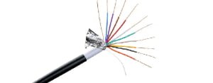
An 8 core alarm cable provides eight independent conductor paths for multi-zone alarm systems, available in both unshielded (RVV) and shielded (RVVP) configurations. The cable's layered structure ensures reliable signal transmission from sensors to control panels while preventing interference.
I have worked with hundreds of security contractors over the past twelve years, and the cable selection often determines system reliability. Let me share what I have learned about 8 core alarm cables and how to choose the right type for your application.
What Are the Main Types of 8 Core Alarm Cables?
The alarm cable market offers two primary categories. One provides basic signal transmission, while the other includes additional protection against electromagnetic interference. Selecting the wrong type can lead to system malfunctions.
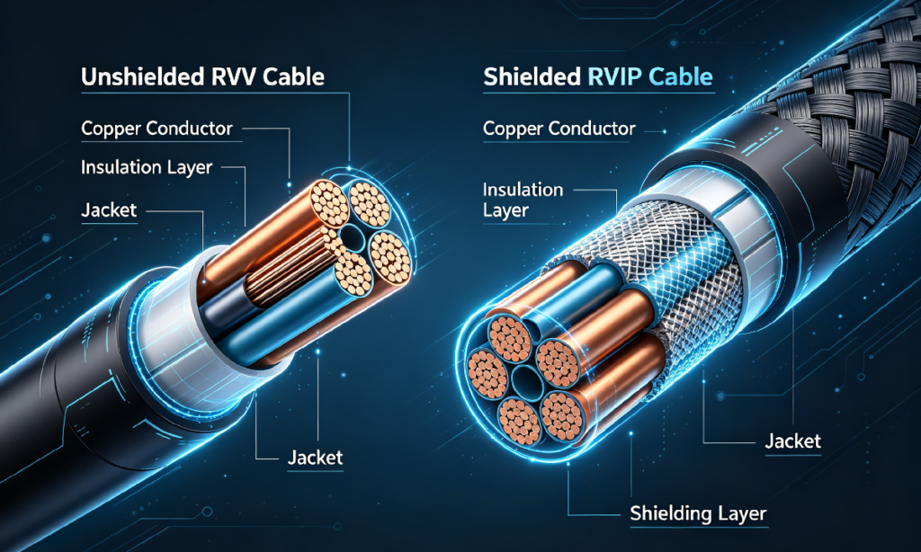
The two main types are unshielded RVV 8-core cables for standard installations and shielded RVVP 8-core cables for environments with electromagnetic interference. Both types feature eight independent conductors but differ in their protective layers.
Understanding RVV vs RVVP Construction
I remember a client who installed RVV cables near industrial motors. The system experienced constant false alarms until we switched to RVVP cables. The shielding made all the difference.
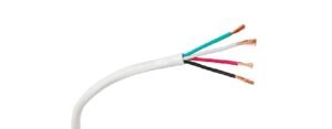
The RVV cable uses a straightforward design with eight insulated conductors bundled together under one outer jacket. This configuration works well in residential buildings and small commercial spaces where electromagnetic interference is minimal. The conductors typically come in different colors for easy identification during installation.
The RVVP version adds a metal shield layer between the bundled conductors and outer jacket. This shield acts as a barrier against external electromagnetic fields from motors, high-voltage lines, and other electrical equipment. A drain wire within the shield connects to ground, channeling interference away from signal conductors.
| Feature | RVV 8 Core | RVVP 8 Core |
|---|---|---|
| Shielding | None | Aluminum foil or copper braid |
| EMI Protection | Basic | High |
| Flexibility | More flexible | Slightly stiffer |
| Cost | Lower | 15-25% higher |
| Applications | Residential, low-EMI areas | Industrial, high-EMI zones |
How Is an Unshielded 8 Core RVV Alarm Cable Structured?
The internal architecture of an alarm cable determines its performance. Each layer serves a specific purpose in protecting signals and maintaining cable integrity. Understanding this structure helps you evaluate cable quality.
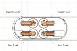
An unshielded RVV 8 core alarm cable consists of four main layers from inside out: oxygen-free copper2 conductors, individual PVC insulation, optional filler material, and an outer PVC jacket. The eight conductors are arranged in four pairs for positive and negative signal pairing.
Breaking Down Each Layer
The conductor core forms the foundation of signal transmission. We use oxygen-free copper in cross-sections of 0.5mm² or 0.75mm² depending on transmission distance requirements. The conductors can be solid single-strand or stranded multi-strand construction. I prefer stranded conductors for installations requiring frequent bending or movement.
Each conductor receives individual PVC or PE insulation coating through an extrusion process. This insulation prevents short circuits between adjacent conductors. We apply different colors to each insulated conductor. The standard color sequence includes black, red, blue, yellow, white, brown, green, and gray. This color coding simplifies installation work and troubleshooting.
Between the insulated conductors and outer jacket, manufacturers may add PP cotton or rubber-plastic filler material. This filler occupies void spaces created when twisting eight conductors together. The filler provides three benefits. It maintains round cable shape under pressure. It increases crush resistance during installation. It prevents conductor deformation when the cable bends around corners.
The outer PVC jacket encapsulates all internal components. This protective layer provides waterproofing, abrasion resistance, and protection against physical damage during handling and installation. The jacket thickness typically ranges from 0.8mm to 1.2mm depending on the application environment.
What Additional Protection Does a Shielded RVVP Cable Provide?
Electromagnetic interference poses a serious threat to alarm system reliability. Motors, transformers, and high-voltage cables generate electromagnetic fields that can induce false signals in unshielded alarm cables. Shielded cables offer a solution.
Shielded RVVP 8 core alarm cables add two critical components: a metal shield layer (aluminum foil wrap or copper braid mesh) and a drain wire for grounding. These components block external electromagnetic interference while maintaining all the structural features of RVV cables.
![RVVP shielded cable structure]()
Shield Layer Construction Methodshttps://doublewincables.com/shielded-alarm-cable-showing-metal-shield-layer-and-drain-wire/
I have tested both aluminum foil and copper braid shields in factory environments. Each type offers distinct advantages depending on the installation requirements.
The aluminum foil shield consists of a thin metallic tape wrapped completely around the bundled insulated conductors. This wrap provides 100% coverage with no gaps. The aluminum foil method offers excellent high-frequency interference rejection. It keeps the cable diameter smaller and maintains flexibility. However, aluminum foil can tear during rough handling or repeated bending.
The copper braid shield uses fine copper wires woven into a mesh sleeve surrounding the conductor bundle. The braid typically achieves 85-95% coverage depending on weave density. This construction provides superior low-frequency interference rejection. The copper braid withstands physical stress better than foil. It also offers lower DC resistance for the shield path. The trade-off is increased cable diameter and reduced flexibility.
Some manufacturers combine both methods in a composite shield design. The aluminum foil provides complete coverage while the copper braid adds mechanical strength. This combination delivers optimal performance but at higher cost.
| Shield Type | Coverage | Flexibility | Frequency Range | Durability |
|---|---|---|---|---|
| Aluminum Foil | 100% | High | Best for high-freq | Tears easily |
| Copper Braid | 85-95% | Medium | Best for low-freq | Excellent |
| Composite | 100% | Low | Full spectrum | Excellent |
The Critical Role of Drain Wire
The drain wire completes the shielding system. This bare or tinned copper conductor runs in contact with the shield layer along the cable length. During installation, the drain wire connects to the system ground at the control panel end. Any electromagnetic interference captured by the shield flows through the drain wire to ground rather than affecting signal conductors. Without proper drain wire grounding, the shield loses most of its effectiveness.
What Are the Specialized Variants of 8 Core Alarm Cables?
Standard PVC-insulated alarm cables meet most general requirements. However, certain environments demand additional fire safety features or mechanical protection. I have supplied specialized cables for subway stations, chemical plants, and underground installations.
Specialized 8 core alarm cable variants include LSZH (Low Smoke Zero Halogen) versions for enclosed spaces and armored versions for direct burial applications. LSZH cables use flame-retardant compounds producing minimal smoke and no toxic gases during fire, while armored cables add a galvanized steel tape layer for rodent and crush protection.
LSZH Cable Construction for Fire Safety
I supplied LSZH alarm cables for a hospital renovation project last year. The specification required cables that would not generate toxic fumes in case of fire. The project manager explained that smoke inhalation causes more casualties than burns in building fires3.
LSZH cables replace standard PVC insulation and jacketing with halogen-free polymer compounds. These materials typically consist of polyolefin or modified polyethylene formulations. During combustion, LSZH materials produce water vapor and carbon dioxide instead of hydrochloric acid4 and other toxic gases. The smoke emission is reduced by 70-80% compared to PVC5.
The fire safety benefits come with trade-offs. LSZH compounds have lower UV resistance than PVC, making them less suitable for outdoor exposure. The material is also less flexible at low temperatures. LSZH cables typically cost 20-30% more than equivalent PVC versions. Despite these limitations, building codes in many regions now mandate LSZH cables for public buildings, transportation facilities, and high-occupancy structures.
Armored Cable Design for Harsh Environments
Direct burial applications present unique challenges. Underground cables face threats from soil moisture, rocks, ground settling, and rodents. I worked on a perimeter security project where standard cables failed within six months due to rat damage.
Armored alarm cables add a galvanized steel tape layer between the shield and outer jacket. The steel tape is typically 0.15-0.2mm thick and corrugated for flexibility. This armor layer provides crush resistance up to 500N per centimeter and prevents rodent teeth from reaching the conductors.
The armor increases cable weight and stiffness. Installation requires wider bending radii and more careful handling. Armored cables need special termination techniques at both ends to properly ground the armor without creating ground loops. Despite these complications, armored construction extends cable lifespan from 3-5 years to 15-20 years in underground installations.
Where Do 8 Core Alarm Cables Find Typical Application?
The eight independent conductors in these cables enable simultaneous connection of multiple security devices. I have designed systems ranging from small shops with four zones to factories with complex multi-building coverage.
8 core alarm cables primarily serve multi-zone security systems where eight conductors accommodate multiple detector inputs. Common applications include alarm panel wiring for 4-8 protection zones, smoke detector networks, door contact loops, and motion sensor arrays. Shielded versions are essential in industrial facilities with heavy electrical equipment.
Multi-Zone Alarm System Configuration
A typical four-zone residential alarm system uses one 8 core cable from the control panel to a central junction point. Each pair of conductors (positive and negative) connects to one protection zone. Zone 1 might cover the front entrance with a door contact and motion sensor wired in series. Zone 2 protects the back door. Zone 3 monitors garage windows. Zone 4 covers the basement.
This configuration reduces installation time and cable clutter compared to running separate two-conductor cables for each zone. The installer pulls one cable instead of four. The color-coded conductors simplify termination work at both ends.
In commercial buildings, eight conductors can support eight individual point-type smoke detectors wired in parallel. The system monitors all eight locations through a single cable run. If any detector activates, its unique resistance signature identifies the specific location to emergency responders.
Industrial Environments Requiring Shielded Cables
I visited a textile factory where the client complained about false alarms every time specific machines operated. The alarm cables ran alongside 380V motor power lines in the same cable tray. The electromagnetic fields from motor starting current induced voltage spikes in the unshielded alarm cables.
We replaced the RVV cables with RVVP versions and installed them in grounded metal conduit where possible. The false alarm rate dropped from 15-20 per week to zero. The factory manager calculated that the cable upgrade paid for itself within three months through eliminated production disruptions and reduced security service calls.
Manufacturing facilities, data centers, power substations, and medical imaging centers all generate significant electromagnetic interference. These environments require shielded alarm cables as a minimum standard. Some applications with extreme interference may need additional mitigation like separate conduit runs or fiber optic alarm transmission.
How Do You Select the Right 8 Core Alarm Cable Specification?
Choosing cable specifications requires matching conductor size, insulation type, and shield configuration to your specific installation requirements. I use a systematic approach to prevent over-specification or inadequate performance.
Cable selection depends on three primary factors: transmission distance, environmental conditions, and electromagnetic interference levels. Conductor size increases with distance (0.5mm² for runs under 100m, 0.75mm² for longer runs), while shield type selection depends on nearby electrical equipment and interference measurements.
Calculating Conductor Size Requirements
Signal voltage drop limits the maximum transmission distance for a given conductor size. Alarm panels typically operate at 12V or 24V DC with current draw of 10-50mA per zone depending on connected devices. I use the formula: Voltage Drop = (2 × Length × Current × Resistance) / 10006.
For a 150-meter cable run carrying 30mA at 12V with 0.5mm² conductors (resistance 36Ω per kilometer)7, the calculation yields: (2 × 150 × 0.03 × 36) / 1000 = 0.324V drop. This represents 2.7% loss, which is acceptable. However, doubling the distance to 300 meters creates 0.648V drop or 5.4% loss, which may cause unreliable operation.
The solution is upgrading to 0.75mm² conductors with 24Ω per kilometer resistance. At 300 meters, the voltage drop reduces to 0.432V or 3.6%, restoring reliable operation. For runs exceeding 400 meters, consider 1.0mm² conductors or installing a mid-point power supply.
Environmental Considerations
Outdoor installations require UV-resistant PVC jacketing and potentially sunlight-resistant insulation compounds. I specify UV-stabilized cables for any runs exposed to direct sunlight, even under roof overhangs.
Temperature ratings matter in extreme climates. Standard PVC cables operate from -15°C to +70°C8. For outdoor installations in northern regions or near heat sources, specify cables rated for -40°C to +105°C using modified insulation compounds.
Moisture exposure determines whether to specify cables with moisture-blocking features. Standard cables rely on the PVC jacket as a moisture barrier. For conduit installations below grade or in wet locations, consider cables with waterproof tape under the jacket or gel-filled conductor spaces.
Chemical exposure in industrial settings may require special jacket materials. Standard PVC resists most oils and weak acids. Exposure to strong solvents, concentrated acids, or petroleum products requires consultation with the cable manufacturer about compatible jacket materials.
| Application | Conductor Size | Shield Type | Special Features |
|---|---|---|---|
| Residential (< 100m) | 0.5mm² | None (RVV) | Standard PVC |
| Commercial (100-200m) | 0.75mm² | Optional | Standard PVC |
| Industrial (any distance) | 0.75mm² minimum | Required (RVVP) | Copper braid shield |
| Direct burial | 0.75mm² minimum | Required | Armored + waterproof |
| Public buildings | 0.5-0.75mm² | Optional | LSZH required |
What Are Common Installation Mistakes to Avoid?
I have inspected hundreds of alarm cable installations over the years. Certain errors appear repeatedly, causing system failures and expensive remediation work. Recognizing these mistakes helps ensure successful installations.
The most critical mistakes include inadequate bending radius causing conductor damage, improper shield termination creating ground loops, and mixed cable types within one system. Minimum bending radius should be 10 times cable diameter, shields must ground at one point only, and all cables in a system should maintain consistent specifications.
Bending Radius Violations
Cable manufacturers specify minimum bending radius for a reason. Bending cables too sharply creates stress points where conductors can break or insulation can crack. I have seen installations where cables made 90-degree turns around sharp building corners with no protection. These installations failed within months.
The standard guideline calls for minimum bending radius of 10 times the cable outer diameter9 for single bends and 15 times diameter for repeated flexing applications. An 8 core alarm cable with 8mm outer diameter requires 80mm minimum radius for fixed installations and 120mm for movable applications.
Use conduit sweeps or rounded cable guides at direction changes. Never force cables around sharp corners or small-diameter pipes. In cable tray installations, provide proper support within 300mm of bends to prevent the cable weight from creating excessive stress at the bend point.
Shield Grounding Errors
Shielded cable effectiveness depends entirely on proper shield termination. The most common mistake is grounding the shield at both ends. This creates a ground loop10 where voltage differences between ground points at opposite ends of the cable cause current flow through the shield. This current generates its own magnetic field, defeating the shield purpose.
Proper technique grounds the shield at the control panel end only. The field end of the cable should leave the shield floating with no connection. Use heats
"[PDF] Intentional Electromagnetic Interference (IEMI) and Its Impact on", https://www.ferc.gov/sites/default/files/2020-05/ferc_meta-r-323.pdf. Electromagnetic interference from external sources can induce unwanted voltages in signal cables, degrading signal-to-noise ratio and causing transmission errors in low-voltage systems. Evidence role: mechanism; source type: education. Supports: Electromagnetic interference can degrade signal integrity in cable systems. Scope note: General principle applicable to alarm cables but not specific to 8-core configurations ↩
"Oxygen-free copper - Wikipedia", https://en.wikipedia.org/wiki/Oxygen-free_copper. Oxygen-free copper (OFC) contains minimal oxygen content (typically <0.001%), providing higher electrical conductivity and better corrosion resistance than standard copper grades. Evidence role: definition; source type: encyclopedia. Supports: Oxygen-free copper has superior electrical conductivity properties. ↩
"Smoke inhalation injury during enclosed-space fires: an update - PMC", https://pmc.ncbi.nlm.nih.gov/articles/PMC4075838/. Fire safety research indicates that smoke inhalation and toxic gas exposure account for the majority of fire-related fatalities, with studies showing 50-80% of fire deaths result from smoke rather than burns. Evidence role: statistic; source type: government. Supports: Smoke inhalation is the leading cause of fire-related deaths. Scope note: Percentages vary by study methodology and fire type; specific statistics depend on jurisdiction and time period ↩
"Low smoke zero halogen - Wikipedia", https://en.wikipedia.org/wiki/Low_smoke_zero_halogen. PVC combustion releases hydrochloric acid and other halogenated compounds, while LSZH materials based on polyolefin compounds primarily produce water vapor, carbon dioxide, and carbon monoxide, significantly reducing corrosive and toxic gas emissions. Evidence role: mechanism; source type: education. Supports: LSZH and PVC cables produce different combustion products. ↩
"Eco-Friendly Choices: Understanding PVC vs. LSZH Cables", https://kmcable.com/eco-friendly-choices-understanding-pvc-vs-lszh-cables/?srsltid=AfmBOoq_HJYnpGQ5uYCJqNg1EThLI-6h70qdkFQAo2VITXdVo2OQ3Bf1. Fire testing under standards such as IEC 61034 demonstrates that LSZH cables produce substantially lower smoke density than conventional PVC cables, with reductions typically in the range of 60-85% depending on formulation and test conditions. Evidence role: statistic; source type: education. Supports: LSZH cables produce significantly less smoke than PVC cables in fire tests. Scope note: Exact reduction percentages vary with specific material formulations, test methods, and fire conditions ↩
"Voltage Drop", https://courses.ems.psu.edu/ae868/book/export/html/967. For two-conductor DC circuits, voltage drop equals twice the one-way length multiplied by current and conductor resistance per unit length (V_drop = 2 × L × I × R), where the factor of 2 accounts for current flow through both supply and return conductors. Evidence role: mechanism; source type: education. Supports: Voltage drop in two-conductor DC circuits follows Ohm's law principles. ↩
"Electrical Wire Gauges", http://hyperphysics.phy-astr.gsu.edu/hbase/Tables/wirega.html. At 20°C, copper conductors with 0.5mm² cross-sectional area have a DC resistance of approximately 36-39 Ω/km depending on conductor construction (solid vs. stranded) and copper purity, based on copper's resistivity of 1.72 × 10⁻⁸ Ω·m. Evidence role: statistic; source type: education. Supports: Copper conductor resistance varies with cross-sectional area. Scope note: Resistance increases with temperature; actual values depend on conductor construction and material specifications ↩
"PVC Cables and Wires | Mechanical & Chemical Characteristics", https://www.sab-cable.com/cables-wires-harnessing-temperature-measurement/technical-data/cables-and-wires/polyvinylchloride-pvc.html. Standard PVC insulation compounds used in cables typically have operating temperature ranges of -15°C to +70°C for fixed installations, with some formulations rated to +105°C for conductor temperature, as specified in standards such as IEC 60227. Evidence role: statistic; source type: education. Supports: PVC cable insulation has defined temperature operating limits. Scope note: Temperature ratings vary by PVC formulation and cable standard; ambient vs. conductor temperature ratings differ ↩
"Minimum Bend Radius | Anixter", https://www.anixter.com/en_us/resources/literature/wire-wisdom/minimum-bend-radius.html. Cable installation standards typically specify minimum bending radius as a multiple of overall cable diameter, commonly 6-10 times diameter for fixed installations and 12-20 times for flexible applications, to prevent conductor damage and insulation stress. Evidence role: expert_consensus; source type: education. Supports: Cable installation standards specify minimum bending radius ratios. Scope note: Specific ratios vary by cable type, construction, and applicable standard (NEC, IEC, manufacturer specifications) ↩
"Ground loops", https://help.campbellsci.com/CR6/Content/shared/Maintain/Troubleshooting/ground-loops.htm. Grounding cable shields at both ends can create ground loops when potential differences exist between ground points, causing circulating currents that generate magnetic fields and may reduce shielding effectiveness at low frequencies, though multipoint grounding is preferred for high-frequency applications. Evidence role: mechanism; source type: education. Supports: Shield grounding configuration affects ground loop formation. Scope note: Optimal grounding strategy depends on frequency range, cable length, and system configuration; single-point grounding is not universally superior ↩