
Choosing multi-conductor cables feels overwhelming when you don't understand the specifications. You worry about selecting the wrong gauge, overpaying for features you don't need, or worse—causing equipment failure that delays your entire project.
The key to selecting multi-conductor cables or multi pair cables lies in matching five core parameters to your application: conductor gauge and material, insulation type, shielding requirements, physical properties like flexibility and temperature range, and electrical performance metrics including impedance and capacitance. Match these correctly, and you avoid costly mistakes while ensuring reliable long-term performance.
I've seen too many customers struggle with control cable selection. They either buy expensive cables with unnecessary features or cheap ones that fail within months. Let me walk you through the exact process we use at our facility to help clients make informed decisions.
What Conductor Gauge and Material Should You Choose for Your Application?
You need to understand wire gauge before anything else. The wrong choice here affects everything downstream—from voltage drop to heat generation and even cable lifespan.
American Wire Gauge (AWG) determines current capacity and voltage drop. Smaller AWG numbers mean thicker wires with higher current capacity. For most industrial applications, 18AWG to 22AWG works well, while control signals often use 24AWG to 28AWG. Choose based on your maximum current draw and acceptable voltage drop percentage.
The relationship between AWG and performance goes beyond simple numbers. Each decrease in AWG number roughly doubles the wire's cross-sectional area. An 18AWG wire carries approximately 10 amperes safely, while a 22AWG handles about 5 amperes. This matters because undersized conductors generate excessive heat and create voltage drops that starve your equipment.
I learned this lesson early in my career. A customer insisted on using 24AWG conductors for a motor control application requiring 8 amperes. The cables overheated within weeks. We replaced them with 18AWG conductors, and the problem disappeared. The voltage drop calculation is straightforward: multiply your current by resistance per foot, then by total cable length. Keep this drop below 3% for power applications and below 1% for sensitive control circuits.
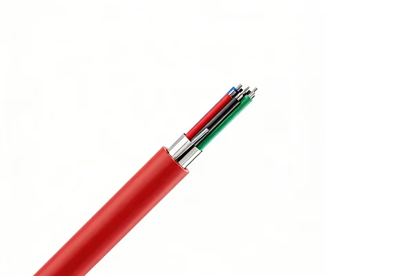
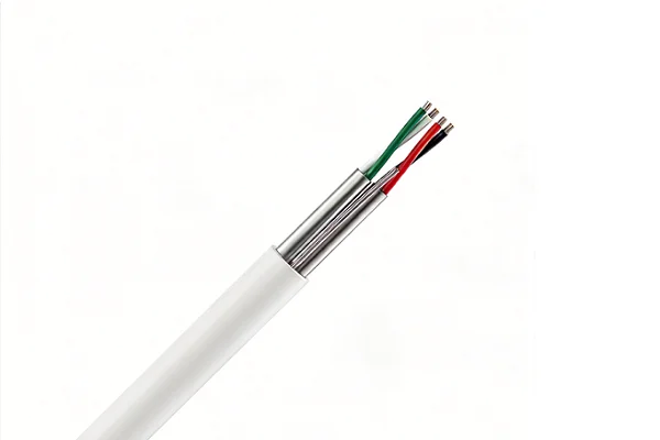
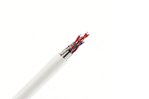
Conductor material creates another critical decision point. Standard copper works for most indoor applications. Tinned copper costs more but resists oxidation and corrosion far better. In our manufacturing facility, we stock both types. Here's how they compare:
| Material | Cost Factor | Oxidation Resistance | Best Use Cases | Typical Lifespan |
|---|---|---|---|---|
| Bare Copper | 1.0x | Moderate | Indoor, climate-controlled | 10-15 years |
| Tinned Copper | 1.3x | Excellent | Marine, outdoor, high-humidity | 20-25 years |
| Silver-Plated Copper | 2.5x | Superior | High-frequency, aerospace | 25+ years |
Tinned copper makes sense for photovoltaic installations and outdoor mounting systems where moisture exposure happens regularly. The upfront cost increase of 30% disappears when you avoid premature replacement. One furniture manufacturer switched to tinned copper for their warehouse automation cables after replacing corroded standard copper cables three times in five years. They haven't had a single failure in the four years since.
Stranding also affects performance and flexibility. Solid conductors work well for permanent installations with minimal movement. Stranded conductors handle repeated flexing much better. For applications requiring cable movement—like robotic arms or sliding doors—choose stranded conductors with at least 19 strands per conductor. This prevents metal fatigue and extends service life significantly.
How Do Insulation Types Impact Cable Performance and Durability?
Insulation protects your conductors and determines where you can safely use the cable. Different materials offer vastly different properties, and choosing wrong here leads to premature failure.
PVC insulation works for general indoor applications with temperatures from -10°C to 70°C and costs the least. XLPE (cross-linked polyethylene) handles higher temperatures up to 90°C and resists chemicals better. For extreme environments, silicone or Teflon insulation withstands temperatures from -60°C to 200°C but costs significantly more.
The insulation thickness matters as much as the material. Standard insulation provides basic electrical isolation. Heavy-duty insulation adds mechanical protection and increases the voltage rating. In our production runs for construction equipment manufacturers, we typically use insulation thickness of 0.38mm for 18AWG conductors in standard applications and 0.76mm for harsh environments.
Temperature rating determines whether your cable survives its environment. PVC becomes brittle at low temperatures and softens at high temperatures. I once consulted with a home appliance manufacturer whose cables failed in their industrial ovens. The PVC insulation melted at the oven's 85°C operating temperature. We switched them to XLPE rated for 90°C, and the failures stopped immediately.
Chemical resistance becomes critical in manufacturing environments. PVC resists water and mild acids but degrades when exposed to oils and solvents. XLPE handles petroleum products much better. Silicone resists almost everything, including ozone. A furniture coating facility needed cables near their spray booth. Standard PVC cables degraded within months from solvent exposure. Silicone-insulated cables in the same location have lasted over three years without issues.
The dielectric strength of insulation affects voltage rating and safety margins. PVC typically withstands 500-600 volts per mil of thickness. XLPE handles 700-800 volts per mil. This means thinner XLPE insulation can replace thicker PVC insulation for the same voltage rating, reducing overall cable diameter and weight. For applications where space is limited—like control panels or cable trays—this difference matters significantly.
Flame resistance varies widely between insulation types. Standard PVC is inherently flame-retardant but produces toxic smoke when burning. Low-smoke zero-halogen (LSZH) materials cost more but meet strict building codes for occupied spaces. Several construction projects we've supplied required LSZH cables for indoor installations, even though PVC would have worked technically. The building codes made LSZH mandatory.
Why Does Shielding Matter and When Do You Actually Need It?
Electromagnetic interference ruins signal quality and causes equipment malfunctions. Shielding blocks interference, but it adds cost and reduces flexibility. You need to know when it's necessary and when it's overkill.
Unshielded cables work fine for power applications and short signal runs in low-noise environments. Add foil shielding for basic protection against high-frequency interference. Use braided shielding for maximum protection and flexibility. Combine both (foil plus braid) for harsh electromagnetic environments like near motor drives or welding equipment.
Shielding effectiveness is measured in decibels. Foil shielding provides 85-100 dB of protection against high-frequency noise but tears easily during installation. Braided shielding offers 70-90 dB protection with much better mechanical strength and flexibility. The braid also provides a low-resistance ground path, which matters for safety.
Coverage percentage determines shielding effectiveness. A 65% braid coverage works for moderate interference environments. High-interference applications need 85-95% coverage. I've worked with photovoltaic mounting system manufacturers who initially used 65% coverage near their inverters. They experienced intermittent control signal issues. Upgrading to 90% coverage eliminated the problems completely.
The shield must connect to ground properly to work. An ungrounded shield does almost nothing. Ground at one end only for low-frequency applications to prevent ground loops. Ground at both ends for high-frequency protection. A common mistake I see is customers installing shielded cable but failing to terminate the shield properly. They wonder why they still have interference problems.
Shielding adds weight and reduces flexibility. A 10-conductor 18AWG cable weighs approximately 45 kg per 100 meters unshielded. Add foil shielding, and weight increases to 52 kg. Add braid shielding on top, and you reach 68 kg. This matters for overhead installations or applications requiring frequent cable movement. The minimum bending radius also increases with shielding—typically from 6 times cable diameter for unshielded to 10 times for shielded cables.
What Physical Properties Determine Installation Success and Long-Term Reliability?
You can choose the perfect electrical specifications but still fail if the cable can't handle the physical demands of installation and use. These properties often get overlooked until problems appear.
Flexibility determines how easily you can route the cable and whether it survives repeated movement. Temperature range must match your environment's extremes. Tensile strength prevents damage during installation. Minimum bending radius affects routing options. Abrasion resistance determines lifespan in harsh conditions.
Flexibility comes from conductor stranding and overall construction. A cable with 7-strand conductors bends more easily than one with solid conductors. Increasing to 19 strands improves flexibility further. For applications requiring continuous flexing—like cable carriers or robotic systems—specify at least 30 strands per conductor. We manufacture cables for automated furniture assembly lines that flex millions of times. These use ultra-flexible construction with 41-strand conductors and special jacketing.
The minimum bending radius prevents damage during installation and use. Bend a cable too sharply, and you damage the conductors or insulation. The general rule is 6 times the cable's outside diameter for single bends and 10 times for repeated flexing. An 8mm diameter cable needs a minimum bending radius of 48mm for installation and 80mm if it moves regularly. I've seen installers damage expensive cables by forcing them around tight corners. The cables worked initially but failed within months from the internal damage.
Temperature range requirements go beyond just the insulation rating. The jacket material also has temperature limits. A cable might have XLPE insulation rated for 90°C but a PVC jacket only rated for 70°C. The lower rating governs the cable's actual temperature limit. Consider both operating temperature and storage temperature. Some cables rated for 90°C operation become brittle if stored below -20°C.
Here's a comparison of common jacket materials and their properties:
| Jacket Material | Temperature Range | Abrasion Resistance | Oil Resistance | Flexibility | Cost Factor |
|---|---|---|---|---|---|
| PVC | -10°C to 70°C | Good | Fair | Good | 1.0x |
| TPE | -40°C to 90°C | Excellent | Good | Excellent | 1.4x |
| Polyurethane | -40°C to 80°C | Excellent | Excellent | Excellent | 1.6x |
| Chloroprene | -25°C to 90°C | Excellent | Excellent | Good | 1.5x |
Tensile strength determines how much pulling force the cable withstands during installation. Standard cables handle 50-70 Newtons per square millimeter. Heavy-duty cables reach 100 Newtons or more. For long cable runs through conduit or installations requiring pulling, specify higher tensile strength. A construction equipment manufacturer had cables fail during installation because installers pulled too hard through long conduit runs. We switched to cables with reinforced construction and aramid strength members. Installation damage disappeared.
Abrasion resistance matters wherever cables rub against surfaces or other cables. Standard PVC jackets work for protected installations. Polyurethane jackets resist abrasion far better for applications like cable trays or outdoor mounting systems. In our experience with photovoltaic installations, standard PVC jackets wear through within 2-3 years from wind-induced movement against mounting hardware. Polyurethane jackets in the same conditions last 8-10 years.
UV resistance becomes critical for outdoor applications. Standard PVC degrades from sunlight exposure. UV-resistant PVC adds stabilizers that extend outdoor life from 2 years to 5-7 years. For permanent outdoor installations, specify UV-resistant materials or plan for cable replacement as part of maintenance schedules.
How Do You Match Electrical Performance Metrics to Your Application Requirements?
The electrical characteristics determine whether your cable transmits power or signals properly. Get these wrong, and you face voltage drops, signal distortion, or electromagnetic compatibility issues.
Conductor resistance affects voltage drop and heat generation. Capacitance between conductors limits signal frequency and causes distortion. Impedance matching prevents signal reflections in high-frequency applications. Current rating determines maximum safe amperage. All these parameters must align with your application's electrical requirements.
Conductor resistance follows a simple rule: smaller AWG numbers mean lower resistance. An 18AWG copper conductor has approximately 6.4 ohms per 1000 feet at 20°C. A 22AWG conductor has about 16.1 ohms per 1000 feet. This resistance directly affects voltage drop and power loss. For a 100-foot cable run carrying 5 amperes, an 18AWG conductor drops 3.2 volts, while a 22AWG conductor drops 8.05 volts. This difference often determines whether equipment operates properly.
Temperature affects resistance significantly. Copper resistance increases about 0.4% per degree Celsius. A cable operating at 60°C has roughly 16% higher resistance than the same cable at 20°C. Factor this into voltage drop calculations for cables carrying continuous current or operating in hot environments. I've troubleshot systems where voltage drop calculations looked fine on paper but failed in practice because engineers forgot to account for elevated operating temperatures.
Capacitance between conductors matters for signal transmission. Higher capacitance limits the frequency response and causes signal distortion. Standard multi-conductor cables have capacitance around 30-50 picofarads per foot between adjacent conductors. Low-capacitance cables designed for high-frequency signals reduce this to 12-20 picofarads per foot through careful conductor spacing and insulation selection.
The relationship between capacitance and signal frequency determines maximum cable length for acceptable signal quality. A control signal at 1 MHz can travel much farther than a 10 MHz signal in the same cable. As a rough guide, multiply maximum frequency in MHz by maximum length in meters—the product should stay below 100 for acceptable performance. A 2 MHz signal works fine over 50 meters but distorts significantly over 100 meters in standard cables.
Impedance matching prevents signal reflections and ringing in high-speed digital applications. Standard cables have characteristic impedance around 100-120 ohms. Specialized data cables maintain tighter impedance control—typically 100 ohms ±5%. This consistency matters for Ethernet, USB, and other high-speed protocols. Using standard multi-conductor cable for these applications causes errors and reduced data rates.
Current rating depends on conductor size, insulation type, and installation method. An 18AWG conductor in free air handles about 10 amperes safely. Bundle that same conductor with others in a cable tray, and the rating drops to 7 amperes due to reduced cooling. Enclose it in conduit, and the rating might drop to 5 amperes. Always check current ratings for your specific installation method.
Here's a practical current rating table for common configurations:
| AWG Size | Single Conductor (Free Air) | Bundled in Cable | In Conduit | Maximum Temperature Rise |
|---|---|---|---|---|
| 18 | 10A | 7A | 5A | 30°C |
| 20 | 7A | 5A | 3.5A | 30°C |
| 22 | 5A | 3.5A | 2.5A | 30°C |
| 24 | 3.5A | 2.5A | 1.5A | 30°C |
Voltage rating depends on insulation thickness and type. Standard 600V rated cable uses thicker insulation than 300V rated cable. Higher voltage ratings add cost, weight, and reduce flexibility. Specify the voltage rating you actually need rather than defaulting to the highest available. A 300V rated cable costs 15-20% less than a 600V rated cable with otherwise identical specifications.
Conclusion
Choosing multi-conductor cables requires matching conductor specifications, insulation properties, shielding needs, physical characteristics, and electrical performance to your specific application. Focus on actual requirements rather than over-specifying, verify environmental conditions carefully, and calculate electrical parameters for your exact installation method. This approach prevents costly mistakes and ensures reliable long-term performance.